Accurate, data-rich, and annotated architectural drawings hold great significance for architects, interior designers, and engineers, as they deliver clear visualization of design intent for buildings. These building drawings ensure effective communication, lower errors, and foster quick decision making for the entire project lifecycle.
info@truecadd.com
Types of Architectural Drawings in Building Construction
Table of Contents
In the AEC Industry, multiple architectural drawings work together to form a roadmap for successful project delivery. From concept sketching to in-depth building construction documentation, architectural drafting services convey design intent through drawings, encourage collaboration between multiple participants, and ensure regulatory compliance.
Each type of architectural drawing, including floor plans, site plans, sections and elevations, provides a specific purpose, including spatial arrangement, structural integrity, aesthetics and building systems integration. Understanding architectural drawings and their role in project-wide communication is important for informed decision making through the entire project lifecycle.
What are Architectural Drawings?
Architectural drawings are defined as technical illustrations scaled in 2-dimensions that represent orthographic projections of a planned structure. These building drawings include elevations, floor plans, site plans, landscape drawings, excavation drawings, etc., which adhere to symbology and conventions.
These building drawings deliver detailed information about dimensions, building layout, structural elements, materials, finishes and system integration. Utilized by architects, engineers, contractors and local authorities, these drawings serve as contractual agreements to guide the construction process and ensure compliance with architectural drawing standards, safety standards and building codes.
Moreover, architectural drawings enable the visualization of design intent to facilitate communication, analysis and decision-making between project stakeholders.
The Role of an Architectural Drawing Plan in the AEC industry
Within the contemporary AEC landscape, architectural drawings play a significant role based on technological advancements. They serve as a communication tool that translates abstract design into realistic visual representations comprehensible to multiple stakeholders. As BIM service providers have gained prominence, 2D drawings extracted from 3D BIM models have become essential for regulatory submissions, permit approvals, and on-site coordination.
Furthermore, these drawings function as legal documents to define the project scope, mitigate risks, and delineate contractual obligations. Accuracy and adherence to Architectural drawing standards are important for project success, and to realize precise material quantities, construction methods, aesthetics and functionality.
13 Types of Architectural Drawings
In the world of architecture design and building construction, architect drawings act as a visual language to communicates project vision, technical specifications, and other details. Each architectural drawing delivers a unique purpose that contributes to the detailed realization and understanding of architectural design. Let’s look into each type of drawing and understand its significance.
1. Site Plans
A site plan showcases a detailed view of the project relationship with its external space. It includes existing structures, property boundaries, landscape components, access points, utility lines and building footprints. Site plans are critical to obtain permits, assess environmental impact, and ensure projects latch onto zoning regulations. Site plans also serve as guides for contractors during onsite activities.
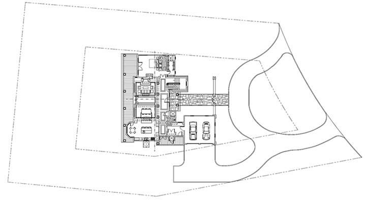 Site Plan
2. Floor Plans
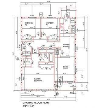
A floor plan is a scaled horizontal depiction of a building layout at multiple levels, outlining the placement of rooms, elevators, corridors, doors, windows, and other fixed components. In the context of 3D floor plan modeling and 3D floor plan rendering, these plans are transformed into realistic, three-dimensional visualizations that enhance spatial understanding and detail. Such 3D visualizations are valuable for interior design, space planning, circulation patterns, and furniture layout, offering stakeholders a more immersive perspective. Floor plans, whether in 2D or 3D, also serve as foundational drawings that inform other critical plans, such as plumbing and electrical layouts.
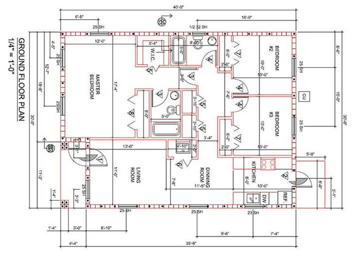 Ground Floor Plan
3. Elevation Drawings
Elevation drawings represent the exterior façade of a building, which is viewed from specific directions (front, side or rear). It represents vertical proportions, materials, heights, rooflines, doors and windows, and other architectural details. Elevations are key to understanding aesthetic appearance, evaluating relationships with the surroundings, and selecting materials.
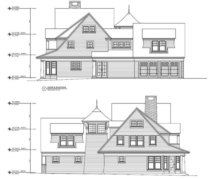 Elevation Drawing
Bring your vision to life with our expert architectural drawing services.
Contact us today to get started →Coordinated and clash-free 3D architectural model for a 4-storey residential project saves project time and costs
An Architectural and Engineering consultant approached TrueCADD for a 4-storey residential project in the UAE. Inputs, including 2D drawings, PDF files, and reference sketches, were provided.
The team built a coordinated and clash-free 3D architectural BIM model at LOD 300 with component linking using tools like Revit and BIM 360. GA drawings were extracted for building sections, elevations, detailed sections, and BOQ’s with accurate quantities.
The deliverables led to:
- Time, cost, and material savings
- Reduction in material waste
- Quick TAT of 4 weeks
- Improved client presentation using 3D models for walkthroughs
- Deliverables with 98.5% accuracy
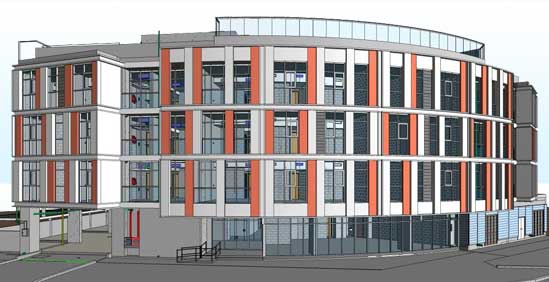 LOD 300 Architecture Model
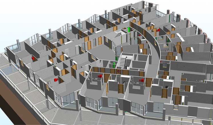 Building Internal Image
4. Sections Drawings
An architectural section drawing depicts a vertical cut through the building that reveals its structure and the relationship between various spaces and floors. It describes the room height, ceiling details, structural components like beams, columns and foundations, and the placement of building components.
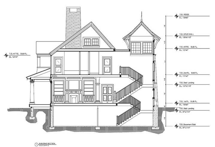 Building Section View
5. Reflected Ceiling Plan (RCP)
A Reflected Ceiling Plan (RCP) is a drawing that illustrates the ceiling layout as reflected on a mirror. It represents the placement of diffusers, sprinklers, light fixtures, HVAC registers, smoke detectors and ceiling-mounted elements. RCP’s are key to coordinating mechanical and electrical systems to ensure appropriate lighting distribution that meets safety code needs.
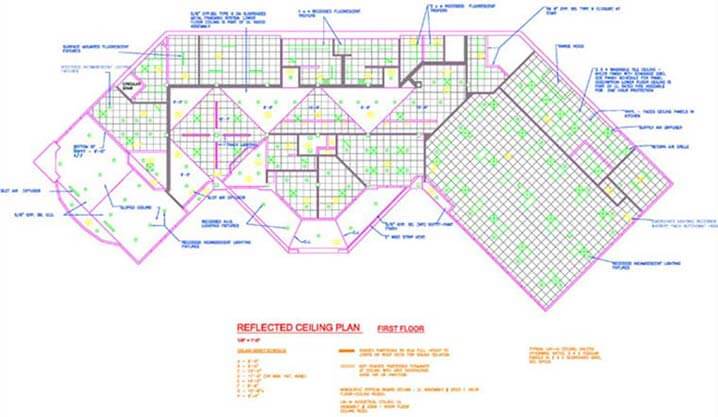 Reflected Ceiling Plan
PDF to CAD conversion of commercial building
An architectural design company from Cincinnati, USA hired TrueCADD for PDF to CAD conversion. With 2D PDF files of floor plans and framework provided, the team at TrueCADD built a CAD model and CAD drawings for 400 floor plans with appropriate QC.
The final deliverables helped the client with:
- Communication improvements with other teams
- Digitized floor plans
- Greater quality that led to project extension to build a BIM model in Revit
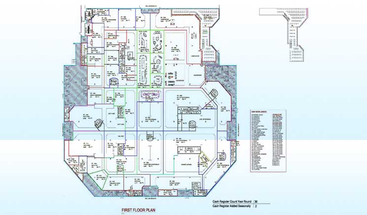 Floor Plan CAD Conversion
Looking for precise and professional architectural drawings? Partner with us for your next project.
Contact us NOW →6. Detail Architectural Drawings
Detail architectural drawings deliver in-depth data about specific building components or assemblies that are complex but showcase larger-scale architect drawings. They represent dimensions, materials, window details, connections, roof assemblies, wall sections and other details to prevent errors and resolve conflicts between multiple building elements.
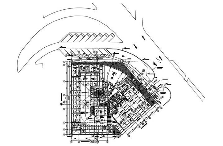 Detail Architectural Drawings
7. Door and Window Schedules
A door and window schedule is represented in a tabular form that outlines various doors and windows. It includes data on every element type, size, material, finish, location, hardware or any other requirement. Door and window schedules streamline the procurement process to ensure material and finish consistency for installation and maintenance.
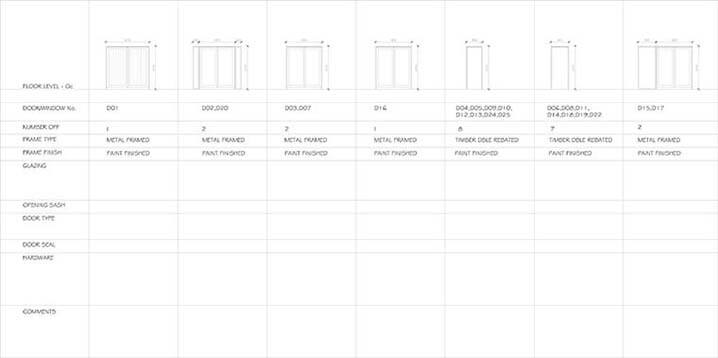
 Door and Window Schedules
8. Finish Schedules
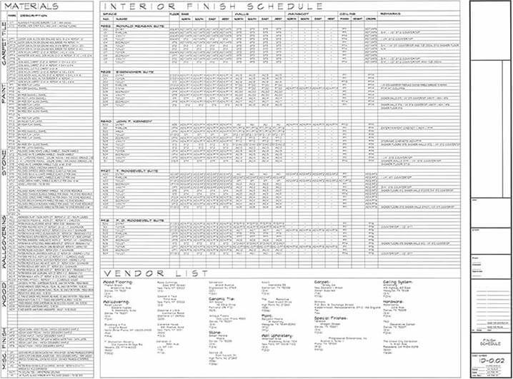
A finish schedule outlines various building aspects in a tabular form like materials and finishes utilized in building areas like ceilings, floors, walls and cabinetry. It specifies flooring materials, wall coverings, and finishes that facilitate efficient installation and maintenance. Finish Schedules are key to ensure a cohesive aesthetic, communication of design intent with contractors, material procurement, and installation.
 Source: lifeofanarchitect.com
Precise approval drawings lead to faster approvals for 500+ residential projects in the US
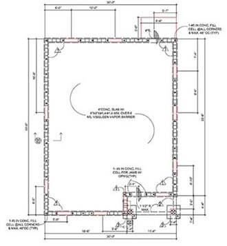
An architectural and construction firm reached out to TrueCADD for a project that constituted 500+ residential projects. Providing 2D designs in .dwg format as input, the team at TrueCADD built approval drawings as per architectural drawing standards. The drawings were signed and submitted for city approval.
The approval drawings:
- Saved costs
- Led to quick TAT of 18 months
- Received a business extension collaboration on multiple projects
 Ground Floor Plan Details
 Foundation Plan Drawing
9. Electrical Plans
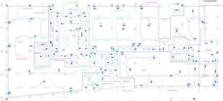
An electrical plan shows locations of switches, outlets, electrical panels, light fixtures, wiring routes and junction boxes. It also includes data on voltages, circuits and wiring routes. Electrical plans are key to coordinating electrical work, ensure equal power distribution, and electrical code needs. Electrical contractors use these plans for installation, while building operators use them for troubleshooting and maintenance.
 Electrical Plans
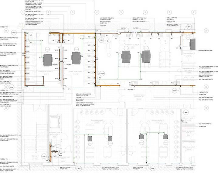
10. Plumbing Plans
A plumbing plan depicts the layout for drainage and water supply pipes, water heaters, fixtures like toilers, showers, sinks and other plumbing components. It represents the position of plumbing equipment, connections, slopes and piping size. Plumbing plans are critical for coordinating plumbing work, meeting plumbing needs, and ensuring water flow. These plans are used by plumbing contractors for installation and by building operators for repairs and maintenance.
 Plumbing Plans
Transform your ideas into detailed architectural plans with our drawing services.
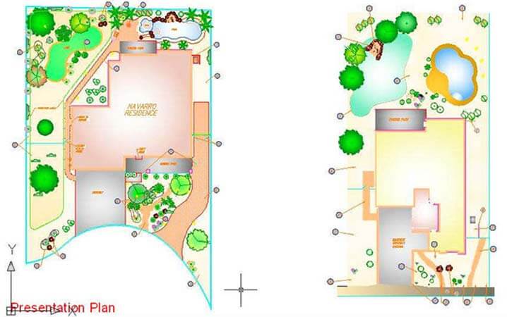
Contact us today →11. Landscape Architectural Drawings
Landscape architectural drawings represent the design and arrangement of outdoor spaces, including elements like trees, plans, walkways, patios and site furnishings. These drawings are created alongside drawing architectural plans, grading details, irrigation, drainage and site lighting systems. These drawings serve as a guide during on-site work to ensure precise implementation of the landscape.
Landscape architectural plans serve as significant deliverables to obtain permits, assess environmental impact, and maintain the landscape.
 Landscape Architectural Drawings
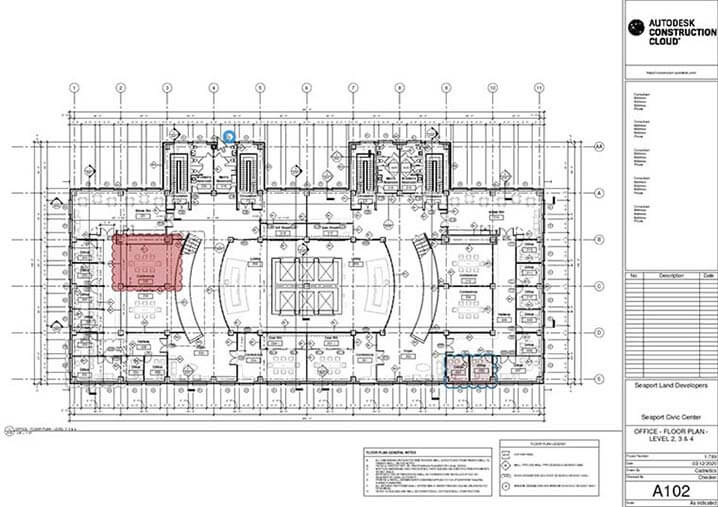
12. As-Built Architectural Drawings
As-Built architectural drawings serve as revised construction documentation sets that reflect the final condition of the project. Incorporating changes made during construction that deviate from the original design intent, these drawings provide an accurate, up-to-date record of the building. As-Built drawings are essential for accurate architectural 3D modeling of facilities, maintenance systems, renovations, and future improvements. They accurately depict existing building conditions, including materials, locations, and dimensions.
 Source: autodesk.com
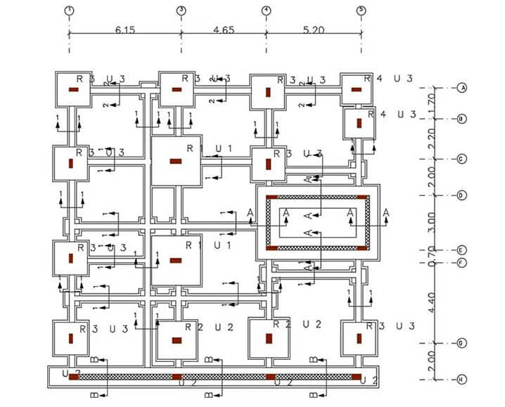
13. Excavation Architectural Drawings
Excavation architectural drawings are specialized site plans that focus on earthwork for a construction project. They represent proposed and existing site contours that indicate excavation areas, grading, filling and location of underground utilities. These drawings detail the slopes and depths of excavations to ensure stability and safety during on-site work. Excavation drawings are crucial for contractors to plan and execute earthwork operations precisely.
 Source: Cadbull
Transform Your Architectural Projects with BIM
Discover how Building Information Modeling (BIM) is revolutionizing design, collaboration, and project delivery in architecture.
Why Download This Whitepaper?
- Stay Competitive: Learn how BIM helps secure complex, high-profile projects.
- Maximize Efficiency: Reduce errors, rework, and costs with smarter workflows and predictive insights.
- Drive Client Satisfaction: Deliver immersive 3D visualizations and ensure compliance with local and international regulations.
- Explore the Future of Architecture: Prepare for the integration of AI, IoT, and advanced analytics into your workflows.
Stay ahead in the competitive world of architecture.
Grab Your Copy Today!Revit: An Industry Leading Software for Extracting Architectural Drawings
Revit, a BIM modeling tool developed by Autodesk, has revolutionized how architectural drawings are created and utilized in the AEC industry. For an architectural BIM services provider, Revit’s advanced parametric modeling capabilities help design in 3D while seamlessly generating 2D drawings like plans, sections, and elevations. This ensures both accuracy and consistency throughout project documentation. With Revit’s intelligent object relationships, real-time design modifications are instantly reflected across the entire model and connected drawings.
By streamlining workflows, minimizing errors, and enhancing collaboration across multiple trades, Revit supports an architectural BIM services provider to improve overall project efficiency. Additionally, Revit’s detailed quantity extraction and scheduling features support precise resource management and cost estimation, allowing for more informed decision-making and optimized project outcomes.
Conclusion
Architectural drawings provide an essential toolkit for translating design concepts into tangible realities. Every drawing type supports a specific function, enabling an architectural drafting company to convey spatial relationships, ensure regulatory compliance, illustrate construction methodologies, and facilitate communication between stakeholders.
As technology evolves, architectural drawings remain at the core of the AEC landscape, guiding various stages of the building process and shaping spaces. By understanding the nuances and purpose of each drawing, architects, contractors, engineers, and clients can leverage the expertise of an architectural drafting company to achieve accurate, efficient, and successful project outcomes.
Need help on an ongoing basis?
We establish long term business relationships with clients and are committed to total customer satisfaction.
