Technical drawings are essential for accurate sheet metal fabrication. Key elements include clear specifications for dimensions, tolerances, materials, finishes and processes like bending and welding. Adhering to industry standards and incorporating DFM principles ensure efficient and error-free production.
info@truecadd.com
How to Prepare Technical Drawings for Sheet Metal Fabricators
Table of Contents
- What to include in sheet metal technical drawings
- How to accurately convey fabrication design intent through technical drafting
- How to optimize designs for sheet metal fabricators with DFM
- Advanced sheet metal drafting considerations
- Ensuring consistent sheet metal fabrication quality in technical drawings
- Wrapping up
Sheet metal fabricators often face issues with technical drawings that carry insufficient information for executing processes with precision. Without accurately prepared sheet metal drafting/drawings, fabricators are forced to rely on guesswork, leading to wasted material, costly rework, and project delays.
Consider technical drawings as the fabrication blueprints for your project. They provide fabricators with all the necessary information to cut, bend and assemble sheet metal components accurately. This is why, when preparing fabrication-ready drawings for sheet metal fabricators, clearly define dimensions, tolerances, material specifications, and finishing requirements, eliminating ambiguity.
When technical drawings for sheet metal design are prepared using SolidWorks, AutoCAD, Inventor or other CAD tools, following the correct methods, they result in faster turnaround times, reduced costs, and a higher quality final product.
In this article, we discuss what to include in sheet metal fabrication documentation to ensure everyone involved in the project understands the goals and possesses the same information.
What to include in sheet metal technical drawings
Detailed sheet metal drawings help fabricators by providing them with a comprehensive view of the fabrication process aligned with the design intent. This is especially important when it comes to complex designs created through sheet metal modeling in SolidWorks, AutoCAD, or Inventor, or other similar CAD software.
The following are the vital elements that help your drawings communicate this effectively:
Title block and drawing information requirements
Title block and drawing information requirements
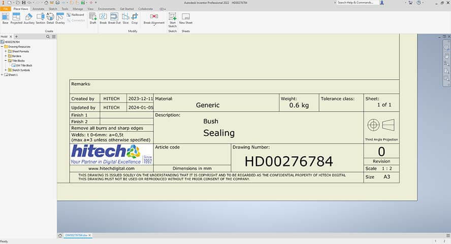
The title block works as your drawing’s identity card in the lower right corner. Your title block needs the drawing number, part description, company details, original scale, and general specifications. For specialized materials or processes, the title block should also include design approval signatures and professional seals.
Critical dimensioning and tolerancing guidelines
Critical dimensioning and tolerancing guidelines
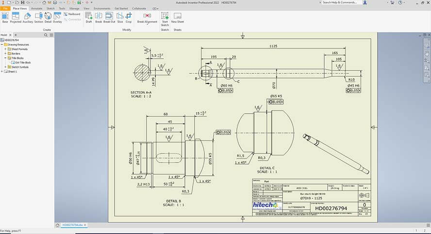
Accurate dimensioning is essential for sheet metal modeling and fabrication to ensure the final product meets the exact design requirements. When dimensioning critical features that impact a part’s form, fit or function, leverage Geometric Dimensioning and Tolerancing (GD&T) to ensure precise control. To maintain accuracy and minimize tolerance stack-up, the dimensions always originate from a single reference point.
Material and finish specification standards
Material and finish specification standards
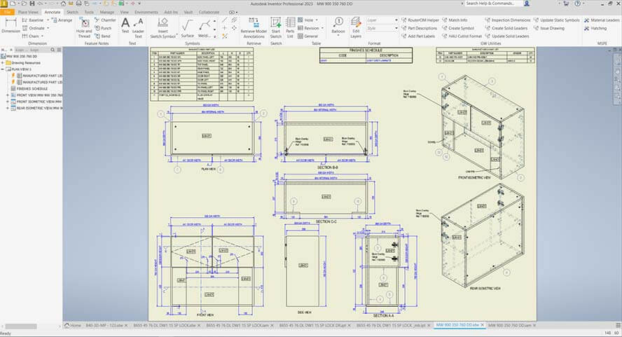
Callouts of material selection for fabrication must specify the type, grade and thickness. Note that stock size thickness tolerance can vary depending on the manufacturer. The finish information is vital; ensure you specify the surface preparation requirements. Include primer specifications, if applicable.
For any paint or powder coat finishes, provide the type and manufacturer designation numbers along with the desired coating thickness. Clearly defined material and finish specifications are crucial for creating accurate sheet metal 3D models and ensuring the final product meets quality and functionality standards.
Bend specifications
Bend specifications
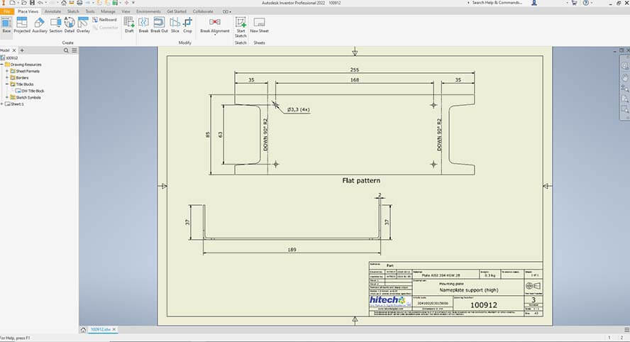
For the best bend execution, it is generally recommended that the inside bend radius be equal to the material thickness. Maintaining a consistent bend radius for all bends on a single part will minimize setup changes and improve efficiency.
Be sure to specify any bend relief requirements, especially when the bends are close to the edges of the part.
Hole and cut-out specifications
Hole and cut-out specifications
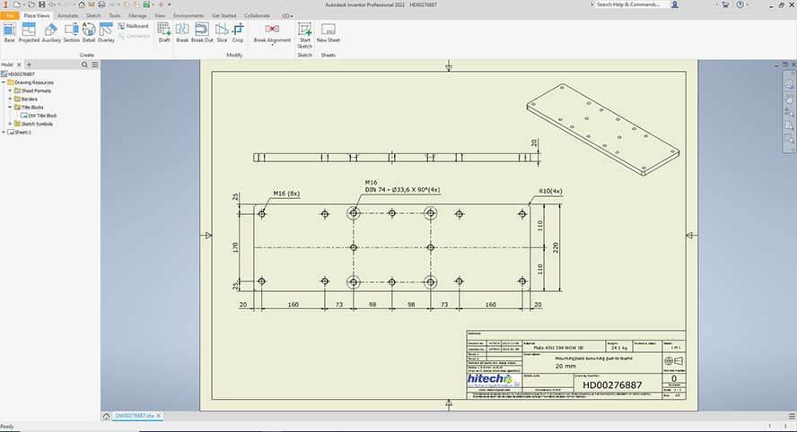
When designing holes and cutouts, the minimum hole diameter should be equal to the material thickness.
For holes less than 1” in diameter, the minimum distance “D” between the hole and the edge of the material should be calculated as 2T + R (where T is the material thickness and R is the hole radius).
For slots or holes greater than 1” in diameter, the minimum distance “D” should be calculated as 2.5T + R.
Forming feature specifications
Forming feature specifications
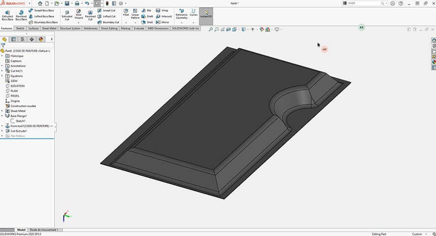
Formed features require a minimum form height, which can be calculated using the formula D = 2.5T + R. While secondary operations might allow for lesser heights, they will substantially increase production costs.
Welding specifications
Welding specifications
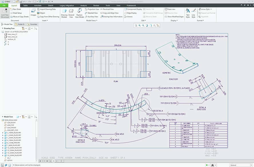
Your welding information must specify the weld type and location. If applicable, include any required heat dissipation techniques. For thin sheet metal, specify the welding techniques to be used and any burn-through prevention methods.
Detailed welding specifications are crucial in sheet metal drafting/drawings to ensure strong and reliable joints in the fabricated part.
The following table lists some examples of weld types, their location and heat dissipation techniques:
| Weld Type | Location | Heat Dissipation |
|---|---|---|
| Fillet | Corner joints |
|
| Spot | Overlapping joints (single spot) |
|
| Seam | Overlapping joints (continuous) |
|
| Stud | Stud to sheet |
|
| Plug | Hole in one sheet, welded through |
|
Simplify sheet metal fabrication processes with our detailed 2D drawings.
Get started now »Hardware specifications
Hardware specifications
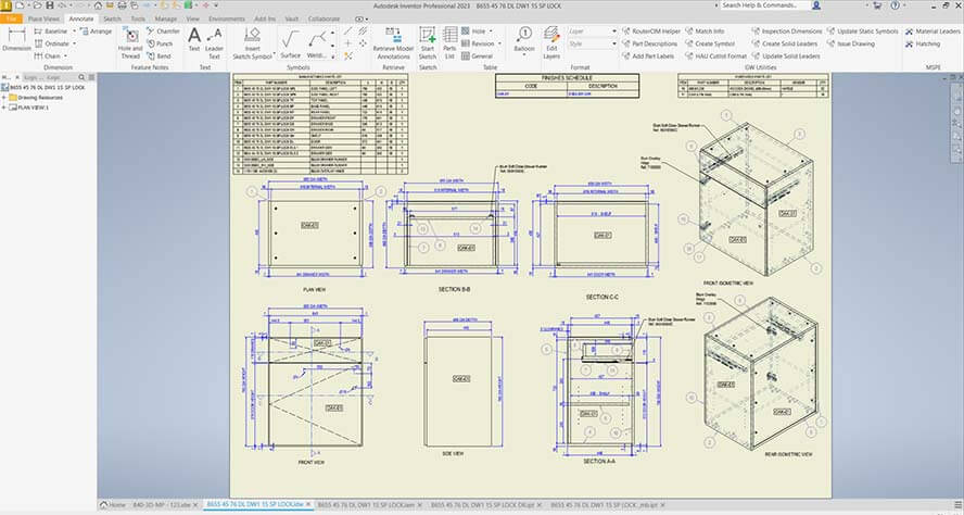
Clearly define all hardware requirements, including PEM nuts and rivet specifications. Provide detailed hardware installation instructions. Where applicable, include torque specifications. Always consider material compatibility to ensure proper function and prevent corrosion.
How to accurately convey fabrication design intent through technical drafting
Following standards
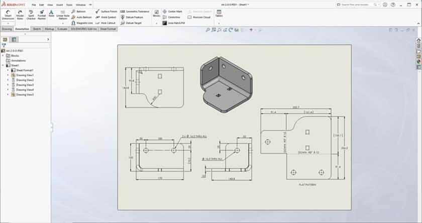
Align technical drawings with industry-recognized standards like ASME Y14.5. These standards serve as the foundation of the universal language of manufacturing, ensuring everyone understands the drawings. Consistency in symbol usage and drawing conventions prevents misinterpretation and reduces questions from fabricators, saving time and resources.
Providing multiple views
Carefully select multiple views to provide a complete and comprehensive understanding of the design to sheet metal fabricators. Primary orthographic views, including front, top and side views, offer fundamental perspectives.
Section views are crucial for revealing internal features that would otherwise remain hidden. Detail views zoom in on complex areas, providing intricate specifics. Isometric views offer a three-dimensional perspective, allowing for better visualization of the overall design.
Accurate dimensioning and tolerancing
You should dimension your parts in a single direction to control tolerance accumulation. When specifying feature-to-feature dimensions, laser cutting tolerance should be +/- .004″. Bend angle tolerance should be +/- 0.5° for standard bends. A minimum spacing of 10mm (3/8 inch) should be maintained from the object to the first dimension.
Always consult your fabricator for optimal tolerances and consider factors like material thickness and bend reliefs in your design.
Providing detailed bend specifications
To achieve accurate final part dimensions, you must precisely calculate both bend allowance (BA) and bend deduction (BD). BA is a function of the material, its thickness and the bend angle. Use BD to determine the developed length.
The K-factor, which indicates the neutral axis location within the material, directly impacts your BA and BD calculations. Selecting appropriate bend radii is critical to prevent stress concentrations that can lead to cracking.
Specialized bending techniques – hemming for reinforcement or edge finishing, flanging to create protruding edges, and joggling to offset sections – demand detailed callouts on your drawings. These callouts must include dimensions, angles and tolerances to ensure accurate fabrication.
Specifying material callouts and finish requirements
Provide precise material specifications with an exact material grade, including its properties and composition. Also, specify the required thickness explicitly.
Special requirements, such as the grain direction for anisotropic materials, must be clearly indicated. The finish details should include surface preparation methods, such as polishing or grinding. Coating specifications, including type, thickness and application method, must be provided.
You should also clearly define the quality requirements for the finish, such as roughness or reflectivity.
Adding clear annotations and notes
To communicate effectively with fabricators, use annotations strategically. Place notes near the features they describe to provide a clear context. A standardized notation system helps ensure consistency and clarity across all drawings.
Highlight critical notes that impact manufacturing decisions or quality requirements. Consider using bold text or other visual cues for emphasis.
Sheet metal drafting documentation needs a logical flow that guides the fabricator through the design. This means that your views, dimensions and notes should help others understand your design intent. Ask yourself if another engineer can build your part accurately using only your drawings. This is a good way to check your work before you send it out.
SolidWorks 3D Modeling for Structural Metal Products, Russia
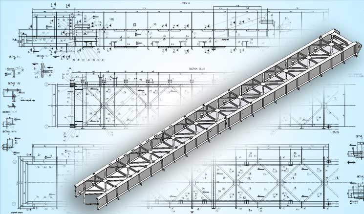
TrueCADD developed detailed drawings and 3D models in SolidWorks for a Russian steel structure manufacturer, processing 1,500 drawings monthly from 2D PDFs and BOMs, enhancing design accuracy and efficiency.
 3D Modeling Steel Structure Manufacturer
How to optimize designs for sheet metal fabricators with DFM
Integrating Design for Manufacturability (DFM) considerations in technical drawings helps optimize sheet metal design for fabricators. The following are some important factors to consider when working with 3D models in sheet metal assemblies in SolidWorks, AutoCAD, Inventor, and other CAD software:
- Material selection: Specify alloys like aluminum for lightweight, corrosion-resistant applications or stainless steel for high strength and temperature resistance. Clearly define the gauge and temper on the drawing.
- Material utilization: Communicate preferred nesting strategies to the fabricator. Consider grain direction for optimal formability, and minimize scrap by arranging parts to maximize material usage. Include a clearly labeled flat pattern drawing.
- Bend order and accessibility: Simulate the bending sequence of metal fabrication in SolidWorks, AutoCAD, Inventor, and other CAD to prevent collisions between the parts and tooling. Ensure sufficient clearances for tooling access, especially for complex geometries. Communicate the desired bend sequence clearly on the drawing.
- Tooling considerations: Design features compatible with standard tooling whenever feasible. If custom tooling is unavoidable, provide detailed specifications and tolerances on the drawing. Indicate preferred tooling radii to minimize stress and cracking.
Save time with accurate cut and shear lists for fabrication.
Contact our experts »Advanced sheet metal drafting considerations
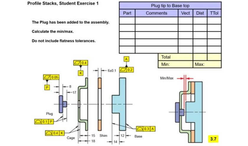 Tolerance stack up analysis in sheet metal drawing (Source:geotol.com)
Ensuring precision in sheet metal fabrication hinges on the clarity and comprehensiveness of your technical drawings. One of the key sheet metal drafting advantages is the ability to precisely communicate design intent and minimize errors. Here are some advanced drawing considerations that leverage these advantages:
A. Springback compensation
Your technical drawings must incorporate springback calculations based on the material’s properties, the sheet’s thickness, and the desired bend radius. Often, FEA simulations can assist in predicting this behavior.
To counteract the springback, we intentionally overbend the part. Clearly specify this required overbending in the drawing. This includes documenting the compensated bend angle and the corresponding adjustments to your tooling – specifically, the die angle and punch radius – needed to achieve that final angle.
For the fabricator to effectively control springback, detailed tooling modifications must be communicated directly on the drawing. This includes specifying die radii and any specialized tooling.
B. Tolerance stack-up analysis
Tolerance stack-up analysis ensures that parts fit together correctly within the allowed variations. This involves calculating the cumulative effect of fabrication tolerances on individual components to determine the overall tolerance range for the assembly.
Advanced techniques for tolerance stack-up analysis include:
- Worst-Case Analysis: This method considers the extreme values of each tolerance to determine the maximum and minimum possible dimensions of the assembly.
- Statistical Analysis: This method uses statistical distributions to model variations in tolerances. This allows for a more realistic assessment of the probability of parts fitting together.
- Monte Carlo Simulation: This method uses random sampling to simulate the assembly process and predict the distribution of the final dimensions.
C. Functional gauging
Instead of inspecting individual dimensions, a functional gauge checks the combined effects of multiple tolerances. This verifies the assembled fit and function directly. Specify gauge requirements by clearly defining acceptance criteria correlated to the part’s intended use.
For example, a gauge for a sheet metal enclosure might simulate mating components to confirm proper clearance and alignment. The drawing should detail the gauge design, including datum features and inspection methods.
GD&T callouts on the part drawing should directly correspond to the gauge’s inspection points. Clearly communicate the gauge’s purpose and acceptance criteria to the fabricator.
Ensuring consistent sheet metal fabrication quality in technical drawings

First Article Inspection (FAI)
FAI, a critical process for validating initial production runs, hinges on comprehensive technical drawings. Drawings must clearly delineate all inspectable characteristics, including dimensions, tolerances, material specifications and surface finishes.
Digital datasets, such as CAD models, facilitate automated inspection and reporting. For sheet metal, specific callouts for bend radii, K-factors, and forming methods are essential.
Integrating with quality control documentation
Integrate quality control documentation directly with the drawing. Reference relevant inspection plans, outlining specific measurement methods and acceptance criteria. Link to control charts, which track process variability and identify trends.
Ensure clear traceability between drawing revisions, inspection results and any corrective actions. Digital thread technologies enable seamless data flow between design, manufacturing and quality. Prioritize clear communication and collaboration between design and quality teams to minimize ambiguity.
Wrapping up
Technical drawings serve as blueprints for successful sheet metal fabrication. Each element-from precise dimensioning to detailed material specifications-plays a vital role in achieving consistent, high-quality results. Your careful documentation directly affects the success of sheet metal fabricators and helps prevent costly production errors.
Effective technical drawings create a clear path for fabricators to deliver exactly what you need by combining proper drawing techniques with design for manufacturability principles. Leveraging sheet metal design services using SolidWorks, AutoCAD, Inventor or other CAD tools further enhance these principles by streamlining the design phase and optimizing it for manufacturing.
Following the best practices discussed will help you transform your technical drawings into complete guides that ensure high quality throughout production.
Need help on an ongoing basis?
We establish long term business relationships with clients and are committed to total customer satisfaction.

