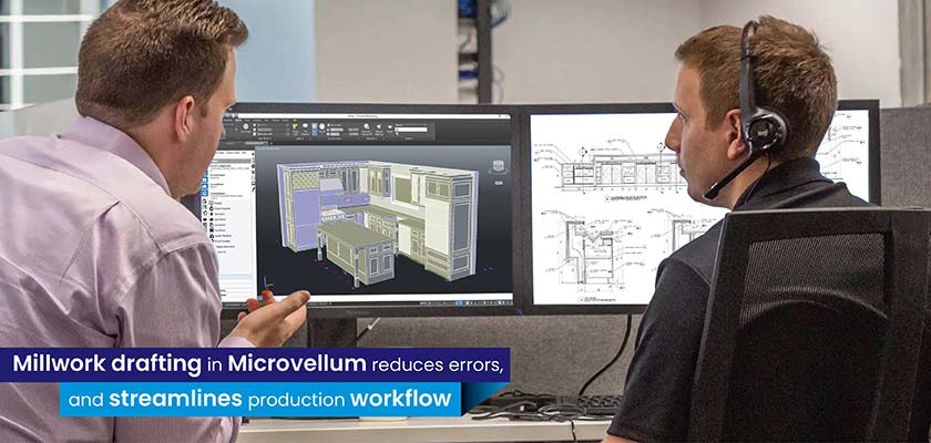
Errors in sheet metal fabrication drawings hamper decision making and adversely impact product quality. Adoption of universal dimensioning practices and detailing for drawings and models promote standardization and clarity of communication across stakeholders.
info@truecadd.com
How Sheet Metal Detailed Drawings Address Concerns for Fabricators
There is a substantial gap between the initial concept sketch and the final model for any building product made of sheet metal. For example, while designing a metal canopy, initial drawings and models pass through an iterative process to meet the customization needs. This includes changes in fundamental canopy frame, design concepts, look and feel etc. before it is released for fabrication.
A majority of these changes come from following Design for Manufacturing (DFM) principles to bridge the gap between design and manufacturing stages. Although revisions consume enormous time, they are indispensable in many cases.

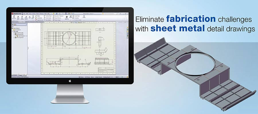
Sheet metal detail drawings developed using CAD tools like SolidWorks, Inventor®, SolidEdge, Creo etc. abide by design rules and enable seamless collaboration. They also address the need for standard methods of dimensioning by following the rules of region-specific and universal drafting practices.
Challenges in sheet metal design for seamless fabrication

1. Need for detailing as per design consideration
Sheet metal fabrication drawings involve major design considerations that the designers need to interpret and depict in the drawings. Bend radius, k-factor, holes positioning, etc. are a few of the many design factors that change with changing thickness of metal sheets.
For instance, while designing an HVAC duct, which is often bent across the building facility, the designing may be affected. In absence of these details in the drawings, operator will have to halt the HVAC metal fabrication every now and then.
2. Emergence of small firms with dimensioning competences
A large part of sheet metal work is done solely by small firms, as in most cases fabrication doesn’t necessitate high-end machining centers. Small companies are entering sheet metal fabrication markets, especially for building products fabrication, but they often lack detailing capabilities. These emerging design drafters often overlook the right approach to detailing and are unaware of global industry best practices.
3. Issues in traditional ways and adopting new design technology
Small building product firms still rely on paper-based drawings. They are erroneous, unreadable at times, and often overloaded with notes, red lines and markups and multiple revisions. Over time they become clumsy. Despite the popularity of digital CAD technology such as 2D and 3D CAD drawings and models, small fabricators still rely on paper-based drawings. In absence of skilled CAD drafters, making the shift is beyond their imagination.
international drawing standards
How 2D/3D CAD resolves detailing challenges in sheet metal drafting
Sheet-metal fabrication units use CAD-CAM integrated environment handled by experienced engineers and a range of matured software. Setting up machines for unique designs and material combinations is a big task.
Many of them use a combination of in-house and outsourced resources and design teams to build the optimal workflow with regard to time, costs and accuracy. Modern and advanced CAD platforms have proved useful for building product designers in creating designs, fabrication drawings for shop floor and seamless design handoffs.
Following sheet metal design rules in 2D drawings
A fabricator needs to make bend deductions based on the tool tolerances, materials, and other factors. So, initial flat pattern dimensions supplied by the designer will mostly be unusable. But 2D sheet metal shop drawings that are developed considering these factors ensure uninterrupted fabrication.
Advanced 2D and 3D CAD platforms are programmed to provide insights for bend dedications, k-factor, and other such considerations for various sheet metals. They help to create accurate shop drawings for products like door and window frames, enclosures etc. without missing any considerations.
Flat pattern considerations
Creating flat patterns before fabrication begins is an important step to showcase bend lines, zones, punch locations, etc. With CAD drawings, creating flat patterns directly from drawings is easy and accurate. Unless drawings are properly dimensioned and detailed, metal fabricators will need an actual part sample or 3D model to process the part, and lead times will increase with multiple design rework cycles.
Create sheet metal drawings with optimal dimensional details
Holistic design communication to the fabricator includes both formed view dimensions and the flat pattern. So, it is always prudent for fabricators to ensure that the product designs they receive from designer meet their tool requirements. In case of door designs, they must be made aware of design standards to ensure meeting industry regulations.
To ensure seamless fabrication at remote shop floors, design drafting teams should include following information in sheet metal drawings:
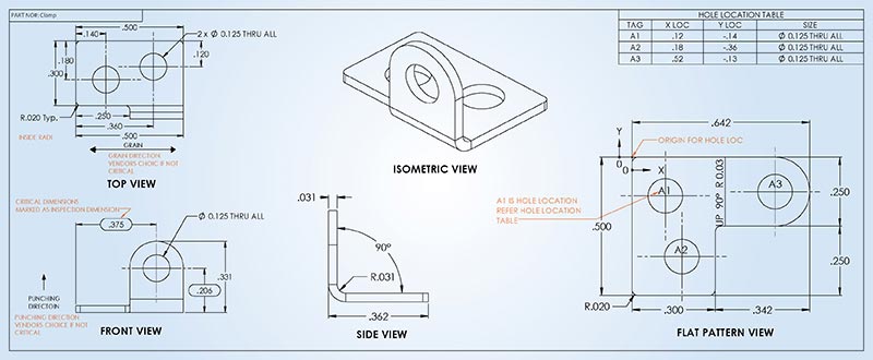
- Drawing must be fully dimensioned and include dimensions for formed bends, holes, flanges, countersinks, and tables for BOMs, holes, slots and bends
- Drawings must show three views of the part –top, front, and sides, and more if so required
- The drawing must have a title block with company name, part description, part number, tolerances, scale, units, etc.
- Clear specification about materials
- Thickness of materials mentioned with accuracy
- In case of material like stainless steel the drawing must show the direction of grain
- Brand and number for powder coating, and other details about finishing
- All tolerances and specifications critical to the fabrication
- Clear details and highlighting of revisions or changes from previous design versions
- Specifications of hardware and torque/Loctite needed for assembly
- In case of multiple parts being made and assembled, an assembly print is required
- Drawing must clearly mark weld locations, welding types and lengths
See below for example of typical details included in sheet metal part drawings:
your sheet metal fabrication project
Getting the correct way of dimensioning in sheet metal fabrication drawings
Best design practices should be followed so that the 3D dimensions match the 2D design. This is of course, now much easier to do with modern CAD software and tools. The following reference pictures and information illustrate the correct dimensioning information to give to a fabricator, and that which a fabricator needs to be sure of.
An example of correct dimensioning:
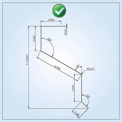
- Must include overall dimensions, bend shapes, and angle and must confirm to a theoretical sharp for exact fabrication needs.
- Dimensions are defined from one point and are easily measureable.
An example of incorrect dimensioning:
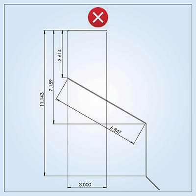
- All dimensions are measured from off bend tangent points and so it is impossible to measure them and fabricate the part accurately.
- Angles are not stated so the bend between two lines or planes cannot be known.
Tips for sheet metal design dimensioning
While there are several thumb rules and guidelines for dimensioning the drawings for sheet metal fabrication, we have enlisted a few important and frequently used aspects.
- Drawings should not have broken geometry when depicting sheet metal parts
- Show grain direction in parts made of stainless steel
- Dimension all formed bends, inside or outside – on the basis of fit with mating pieces, and add REF to the dimension of the last bend
- Ensure current revision matches that shown by the latest artwork or stamp
- Include bend lines where necessary
- Ensure notes do not conflict
- Ensure hardware is compatible with the material type to be used
- Properly dimension countersinks (if any)
- In case of powder coating or paint, the finish must include brand and part number
- Specifications must be shown on plating finish
In sheet metal designing for fabrication of building, it is important to include as much information as possible in dimensional prints. The drafter must be aware of the final application of the product and who is going to read the drawings to include appropriate amount of details.
Gearing up for the next gen sheet metal fabrication needs
Increased personalization has resulted in developing building products with unique parameters, new material combinations and designs requirements. At the same time, deadlines are getting shorter with personalization treated as an ordinary expectation, and little slack given to routine delivery cycle lengths. This pushes the SME segment metal fabricators against tremendous pressure.
In response, sheet metal fabricators are going digital with adoption of advanced CAD-CAM technology for sheet metal detail drawings and cloud-based designing solutions. Stepping into the digital and standardized environment offered by CAD platforms is providing the way for sheet metal fabricators to stay responsive to market needs.
Need help on an ongoing basis?
We establish long term business relationships with clients and are committed to total customer satisfaction.
