Ductwork modeling in Revit overcomes the complex challenges of ductwork design and fabrication. By enabling seamless operations, it simplifies the communication of design intent and facilitates early clash detection.
Leading CAD Outsourcing Company offers solutions of Engineering CAD Services, Design Drafting & 3D Modeling
Email us:
info@truecadd.com
info@truecadd.com
Leading CAD Outsourcing Company offers solutions of Engineering CAD Services, Design Drafting & 3D Modeling
Ductwork Modeling & Fabrication with Revit MEP: A Useful Guide
Updated on February 6th, 2025
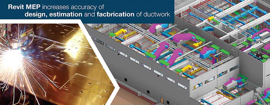
Table of Contents
- AutoCAD vs. Revit for Ductwork Modeling
- How a Coordinated BIM Model Automates the Process
- Streamlining Ductwork Modeling & Fabrication with Revit MEP
- Step-by-Step Guide to Modeling Ductwork in Revit MEP
- Best Practices for Ductwork Modeling in Revit MEP
- Conclusion
- FAQs on Ductwork Modeling in Revit MEP
MEP engineers working on ductwork modeling for complex HVAC systems often face design coordination challenges and inaccuracies. These issues arise due to the difficulty of visualizing the entire ductwork network in traditional 2D designs.
Detailed Revit MEP models ease the generation of shop drawings to facilitate the smooth installation of complex ductwork. Autodesk Revit MEP tools enhance accuracy and collaboration among multiple MEP stakeholders – designers, engineers, manufacturers, contractors, and installers – by offering cost-effective ductwork solutions.
This article discusses how using Autodesk Revit MEP models improves the accuracy and coordination of ductwork design, enabling seamless collaboration among MEP stakeholders. It also explores the benefits of using Revit MEP tools to generate precise shop drawings that streamline installation and reduce errors in complex HVAC systems.
AutoCAD vs. Revit for Ductwork Modeling
While AutoCAD® MEP is commonly favored by MEP technicians for ductwork modeling and fabrication, it is limited by its 2D nature and lack of building information modeling (BIM) capabilities. Let us understand the differences.
| Capability | Revit | AutoCAD |
|---|---|---|
| 3D Parametric modeling | Completely parametric, changes are updated automatically | Limited parametric features |
| Ductwork design | Automated ductwork sizing and layout | Manual ductwork layout |
| Clash detection | In-built clash detection capabilities | Requires manual checks or add-ons |
| Documentation | Automated generation of BOMs and schedules | Manual creation of BOMs and schedules |
| Collaboration | Built for real-time collaboration | Hard to manage shared 3D models |
However, AutoCAD MEP has its own constraints. It cannot produce building information models. Two-dimensional drawings make it hard to visualize complex ductwork networks with multiple elevations. Limited multi-disciplinary coordination and collaboration also delays the fabrication process.
How a Coordinated BIM Model Automates the Process
Revit MEP supports BIM modeling with features like coordination and multidisciplinary model sharing, generation of analysis and pressure reports, fabrication of models, documentation, quantity take-off and scheduling, all of which significantly enhance productivity and operational efficiency.
Revit ductwork modeling allows the inclusion of ducts in various sizes, customized frames, and complex routing and fittings, making it easier to visualize and fabricate HVAC systems accurately.
Revit editing tools like split controls and resizing connected elements also help to develop the model accurately and in less time.
Revit MEP allows for the creation of different types of hangers for ductwork that are attached to those structural elements that are the closest, such as floors, roofs, structural framing, slabs, etc.
MEP 3D Model and Construction Drawings for Residential Building
A US-based engineering firm appointed TrueCADD to create an LOD 400 MEP model of a residential building. The clash-free Revit MEP model led to hassle-free, seamless fabrication and erection of MEP components on the shop floor and on site, respectively.
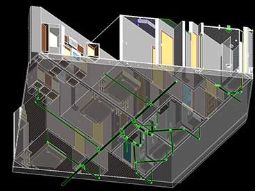 MEP Clash Detection Output
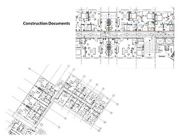 Construction Documents
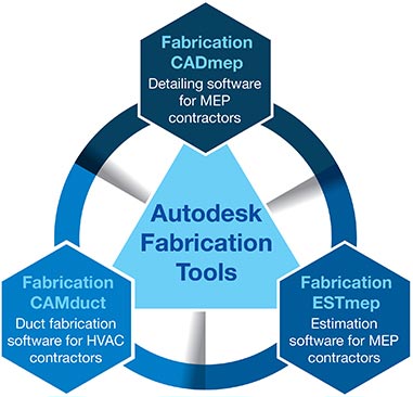
Streamlining Ductwork Modeling & Fabrication with Revit MEP
Fabrication tools help MEP stakeholders export the model for designing, estimating, and fabricating mechanical systems like ductwork, pipework, and electrical containment.
Directly linking Revit MEP model to the tools eases the designing, material management, installation, estimation, and downstream fabrication process. The tools improve visibility and productivity by providing help in tasks like the generation of ductwork networks, creation of detailed slope pipes, vertical annotation, and so on.
Simplify design to fabrication processes for ductwork by using Autodesk Revit MEP.
Contact our MEP BIM experts today »Step-by-Step Guide to Modeling Ductwork in Revit MEP
Modeling ductwork in Revit MEP with a step-by-step approach is crucial. It includes system setup, component placement, routing, interference detection and final verification.
Here are some steps to ensure accurate ductwork modeling in Autodesk Revit MEP:
- Set up the MEP project and link the architectural model
- Define levels, views, and project units for clarity
- Create and configure duct systems
- Place diffusers, terminals, and equipment based on design needs
- Connect the ducts through automated routing
- Calculate offsets, duct sizes, and fittings for enhanced design
- Refine connections with sections views and interference detection
- Apply labels, insulation, and color coding for clarity
- Verify system performance and airflow
- Export and coordinate the model with other trades for interference detection
Best Practices for Ductwork Modeling in Revit MEP
Follow a structured workflow to ensure effective and interference-free ductwork modeling in Revit MEP. Optimize routing, detect clashes quickly, and maintain an accurate classification system for streamlined coordination.
- Utilize worksets and naming conventions for organization
- Ensure Revit families are integrated with accurate parameters and align with project standards
- Reduce fittings, bends, and unnecessary transitions
- Maintain accurate duct elevations to prevent clashes and ensure accessibility
- Detect and resolve clashes early
- Apply multiple filters to view templates for coordination and visualization
- Assign precise pressures, flow rates, and system classifications
- Follow industry standards like ASHRAE and SMACNA for placement and duct sizing
- Use schedules and tags to track materials, system properties, and duct sizes
- Coordinate with architectural and structural models for streamlined integration
Conclusion
Revit MEP’s ductwork modeling capabilities streamline the entire project lifecycle, from design layout to fabrication and installation, ensuring that each phase aligns with the original design intent. This makes it the ideal solution for creating precise and efficient HVAC duct systems.
The software supports designers, engineers, and contractors across MEP disciplines by facilitating a detailed and coordinated building information model of the HVAC and ductwork project. This model also helps in the estimation, analysis, documentation, fabrication and installation. The Revit MEP model can streamline the engineering design process and communicate design intent to stakeholders before construction. Thus, by helping make informed decisions, Revit MEP reduces risk, develops better quality designs, and improves building performance.
Need seamless fabrication and erection of ductwork component for your MEP project?
Contact us NOW »
FAQs on Ductwork Modeling in Revit MEP
-
The key steps to create a ductwork model include setting up the MEP project, placing air terminals, building duct systems, and verifying system connectivity.
-
Utilize the Duct Type properties to define sizes, assign pressure classifications in Mechanical settings, and select the appropriate system types under Duct Systems.
-
Reduce bends and fittings, create proper elevations, and follow industry standards for sizing and layout to enhance airflow.
-
Use the Revit Family Editor in the Systems tab to adjust properties like size, angle, and connection type in the Type Properties panel.
-
Enable the Duct Sizing Tab and input airflow needs for Revit to calculate duct sizes for pressure loss, velocity, and friction criteria.
-
Common mistakes to avoid when modeling ductwork in Revit include avoidance of unconnected systems, excessive fittings, inaccurate elevation and classification and neglecting interference detection, which leads to rework and inefficiencies.
-
Select the duct, go to Properties and assign thickness for lining or insulation. Use Duct Insulation View Filters for visualization.
-
Utilize Worksets, linked models, Interference Check, and view templates to detect interferences early and ensure hassle-free integration with structural elements, electrical and plumbing.
-
Run Interference Check under the Collaborate tab to flag clashes, adjust routing, change elevations, and coordinate with other trades to resolve interferences.
-
Use Schedules in the View tab to list materials, duct sizes, lengths, and system types. Apply filters and sorting to enable accurate documentation and quantity take-offs.
TrueCADD is a premier provider of CAD drafting services and BIM modeling solutions with operations in India, the USA, and the UK. We offer high-quality, cost-effective CAD drafting and BIM outsourcing services to a global clientele, including architects, designers, engineers, surveyors, contractors, manufacturers, fabricators, and building owners. Our extensive in-house capabilities, coupled with vast experience and a robust resource base, enable us to understand and meet the diverse needs of international clients, delivering reliable BIM and CAD outsourcing services across a wide range of industries.
Related Posts


Need help on an ongoing basis?
We establish long term business relationships with clients and are committed to total customer satisfaction.